Here you’ll see a few of the main additive manufacturing pieces of worked on. All of these pieces are uploaded on Sketchfab; to rotate the piece use the left mouse button, and the middle mouse button to pan. When I start to develop a piece, the first thing I have to think about is the viewpoint I want to approach it from, mainly since the CAD work is based on 2D sketches. All of these pieces were done using Creo Parametric 2.0/3.0.
This project was developed during my second year of the aerospace curriculum at the University of Colorado Boulder. The goal of the project was to design a glider from scratch, approaching it from an engineering standpoint. Initially, the team developed code to analyze the aerodynamic properties of the glider. Through trade studies and stability analysis with Solidworks Flow Simulation, the team arrived at the final CAD model presented here. A Microsoft powerpoint of the final presentation for the glider can be downloaded and viewed below.
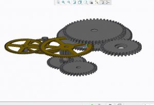
I created this piece late in my junior year of high school with plans I found online. It’s a model RC engine, created by two enthusiasts. I decided to create this piece because I wanted to explore my interest in aerospace. It was difficult to make because of the sheer complexity and number of parts.
The shuttle is made of 2 parts, the boosters, and the shuttle model. I attached it to a base for the 3D print and glued the components together. This piece wasn’t heavily detailed primarily due to a lack of more in-depth measurements, but the scale is accurate. I used this model for a Unity game scene. Using an Oculus Rift viewers are able to get an actual feel for what standing under the shuttle would be like. I presented the scene at MassCUE 2016.
This tank model was made by reverse engineering a toy I had. I used a Vernier Caliper to take all the measurements and accurately recreated it in the program. This model consists of two parts, the body, and the turret. I created a subtle indent so that the turret can rotate when 3D printed.
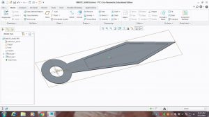
I reverse engineered this model from an actual winged corkscrew. I set out to create an actual articulating piece with the 3D printer, and succeeded. This piece is made up of 8 different parts. I 3D printed each part separately and assembled in by gluing a pin cap onto the end of the pin. The first model didn’t work very well, but with a few altering measurements and some sanding I ended up having a real moving piece.
Senior Project
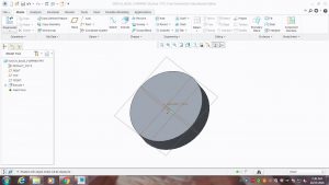
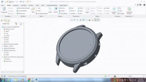
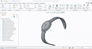
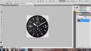
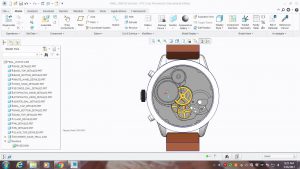
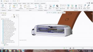
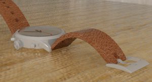
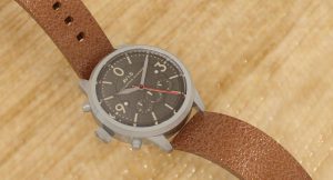
The goal of this project was to design two versions of my watch using computer-aided design software. The first portion was a physical 3D print of my watch, the AVI-8 4024. The second portion was a more detailed replica of the watch, and this was entirely in the CAD software. The paper was about how problem solving and creativity should play a larger role in education. There was be a sub-focus on how “makerspaces” can help expand this. This project was a culmination of the skills I’ve learned through my drafting communications classes. It also expanded my knowledge in project management, design, research, etc.
The process took me roughly 35 hours in just working on the piece. The research for the paper, writing of the paper, working on the poster, meeting with mentors, and etc could push this number up to around 50+ hours.
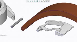
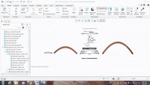
I started by working on the 3D print. I began to take rough measurements of my actual watch using a vernier caliper, and the body began to take shape. I slowly added more details, working on the knobs and the actual watch hands. The bands came next; I shaped them based on the physical bands. I used small pins to connect these pieces together and to allow them to move. Unfortunately because of the flimsy plastic material of the 3D printer, and due to how small the pins were, they broke apart and the final print did not work. A better redesign would use metal pins.
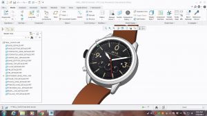
After the 3D print, I began to work on the more detailed CAD version. I imported the same design I used for the 3D print and began to texture it. I created a watch movement based off some designs I found online for a different variant of watch. The movement wasn’t completed in its entirely, it was more just for show. I then created an animated video of the watch using the explode feature that Creo Parametric offers.
The final project came out nicely, despite a few shortcomings I am more than happy with my results. I’ve attached a few links to various work I’ve completed during the year. Most of these items are required through my senior seminar class.
Project Proposal JashanChopra
Background-Research-Presentation
Log Descriptions
Timelog